

In modern mechanical power transmission, the gearbox reducer is an indispensable component that converts high-speed, low-torque motor output into low-speed, high-torque motion suitable for industrial machinery. While the term “gear box” broadly describes any enclosed gear train, the internal structural design varies dramatically across types. Engineers must understand these structural differences to select the right unit for torque density, efficiency, noise level, and spatial constraints. This article examines six widely used gearbox reducer architectures—spur, helical, bevel, worm, planetary, and cycloidal—and illustrates their real-world applications.
1. Spur Gear Reducer
The spur gear reducer is the most fundamental gear box design. It employs straight-cut teeth arranged parallel to the gear axis. When two spur gears mesh, the full face width of each tooth engages simultaneously, creating a direct rolling contact between parallel shafts.
Structural Characteristics: The simplicity of this structure results in low manufacturing cost and straightforward maintenance. However, because the teeth engage instantaneously along the entire contact line, the transmission produces noticeable impact, noise, and vibration. Consequently, spur gear reducers cannot sustain heavy loads at high speeds without excessive wear.
Applications: Due to these limitations, spur gear reducers are best suited for low-speed, light-load, and general-purpose equipment such as small printing machinery, simple conveyor systems, and basic automation devices where cost is the primary concern and acoustic performance is secondary.
2. Helical Gear Reducer
The helical gear reducer improves upon the spur design by cutting teeth at an angle (helix) relative to the gear axis. This seemingly minor geometric change fundamentally alters the transmission dynamics.
Structural Characteristics: As helical gears rotate, the leading edge of each tooth makes contact first, and engagement progresses gradually across the tooth face. This progressive meshing eliminates the instantaneous rigid impact found in spur gears, yielding significantly smoother and quieter operation. The angled teeth also distribute load across multiple teeth simultaneously, increasing load capacity and transmission efficiency. A trade-off is the generation of axial thrust along the shaft, which requires thrust bearings to manage the additional force.
Applications: Because of their quiet, continuous-duty stability, helical gear reducers dominate industries where machinery runs for extended periods. Typical applications include long-distance belt conveyors, cement mixers, chemical processing agitators, water pumps, and food processing lines. The helical gear box is often considered the most versatile general-purpose industrial reducer.
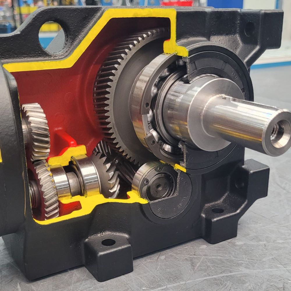
Figure 1: Cutaway view of a helical gear reducer showing the angled tooth engagement and multi-stage gear arrangement.
3. Bevel Gear Reducer
When power must be redirected by 90 degrees, the bevel gear reducer becomes essential. This type uses conical gears with teeth cut along a tapered surface, allowing torque transfer between intersecting shafts.
Structural Characteristics: Bevel gears redirect motion through rolling contact along angled paths on conical surfaces. Spiral bevel variants incorporate curved teeth similar to helical gears, enabling progressive engagement and smoother operation than straight bevel designs. The compact right-angle layout saves longitudinal installation space, making the bevel gear gearbox reducer ideal for machinery where the motor cannot be mounted directly behind the driven equipment.
Applications: Bevel gear reducers are commonly found in lifting machines, vertical mixers, mining conveyors, bucket elevators, and material handling systems. Any application requiring a change in power direction within a confined footprint benefits from this architecture.

Figure 2: Bevel gear reducer showing the conical gear mesh that enables 90-degree power transmission.
4. Worm Gear Reducer
The worm gear reducer operates on a fundamentally different principle from conventional parallel-axis gears. It consists of a threaded worm shaft meshing with a worm wheel (resembling a spur gear) at a 90-degree angle.
Structural Characteristics: Power transmission relies primarily on sliding contact between the worm threads and the wheel teeth rather than rolling contact. This sliding action enables extremely high single-stage reduction ratios—often 30:1 to 100:1—in a remarkably compact package. A distinctive feature is self-locking: at low lead angles, the worm can drive the wheel, but the wheel cannot back-drive the worm, providing inherent braking without external mechanisms. The downside is significant friction, which reduces efficiency (typically 50–90%) and generates considerable heat during continuous operation.
Applications: Worm gear reducers excel in intermittent-duty applications requiring high reduction and load-holding capability. Common uses include lifting platforms, elevator hoists, industrial gates, small conveyors, packaging machinery, and indexing devices. Their compact footprint and self-locking property make them irreplaceable in safety-critical lifting systems.
Figure 3: Cross-section of a worm gear reducer illustrating the worm shaft, worm wheel, and orthogonal shaft arrangement.
5. Planetary Gearbox Reducer
Among all gearbox architectures, the planetary gearbox reducer stands out for its exceptional torque density and precision. Named after its resemblance to a solar system, this design features a central sun gear, multiple planet gears orbiting around it, and an outer ring gear that meshes with the planets.
Structural Characteristics: The sun gear receives input from the motor shaft. As it rotates, it drives the planet gears, which simultaneously roll along the stationary ring gear. A planet carrier connected to the planet gears delivers the output. Because torque is shared among three or four planet gears, the load distributes evenly across multiple mesh points. This coaxial arrangement delivers the highest torque-to-volume ratio of any conventional gear box, with efficiencies often exceeding 95%. The design also offers extremely low backlash and high torsional stiffness, though it demands precise manufacturing and assembly.
Applications: The planetary gearbox reducer is the preferred choice wherever space is limited but power requirements are high. It is ubiquitous in robotic joints, CNC machine tools, mobile crane slewing drives, excavator swing mechanisms, wind turbine yaw systems, and servo-driven automation lines. Its precision and stiffness make it indispensable for motion control applications requiring accurate positioning.
Figure 4: Exploded view of a planetary gearbox reducer showing the sun gear, planet gears, and ring gear architecture.
6. Cycloidal Speed Reducer
The cycloidal speed reducer abandons conventional gear teeth entirely, replacing them with a unique epicycloid mechanism.
Structural Characteristics: An eccentric input shaft drives a cycloidal disc with specially profiled lobes. As the disc rotates eccentrically, its lobes engage with fixed ring pins arranged around the housing. The disc’s motion is transferred to an output pin disc via roller bearings. The reduction ratio is determined by the difference between the number of ring pins and disc lobes. This design achieves high reduction ratios in a single stage while engaging multiple teeth (or lobes) simultaneously, providing outstanding shock-load resistance and near-zero backlash. Unlike conventional gearboxes, cycloidal drives cannot be back-driven, adding a safety feature similar to worm gears but with far higher efficiency.
Applications: Cycloidal reducers serve heavy-duty industrial equipment subjected to impact and vibration. They are found in screw conveyors, bulk material feeders, mixers, rotary presses, packaging lines, and robotics actuators. Industries such as mining, automotive assembly, and aerospace favor cycloidal drives for their durability and compact reliability under fluctuating loads.
Figure 5: Exploded view of a cycloidal drive showing the eccentric shaft, cycloidal disc, fixed ring pins, and output pin disc.
Comparative Summary
| Gearbox Type | Shaft Arrangement | Efficiency | Key Advantage | Best For |
|---|---|---|---|---|
| Spur | Parallel | Moderate | Lowest cost | Light-load, low-speed general machinery |
| Helical | Parallel | High (95–98%) | Smooth, quiet, continuous duty | Conveyors, mixers, pumps |
| Bevel | 90° intersecting | High | Direction change in compact space | Lifting, vertical mixers, mining |
| Worm | 90° crossed | Low–Moderate | High ratio, self-locking | Hoists, gates, elevators |
| Planetary | Coaxial | Very High (>95%) | Highest torque density, precision | Robotics, CNC, wind turbines |
| Cycloidal | Coaxial | High | Shock resistance, zero backlash | Heavy conveyors, presses, robotics |
Conclusion
Selecting the right gearbox reducer requires more than comparing catalog specifications—it demands an understanding of how internal structure dictates performance. Whether the priority is the whisper-quiet operation of a helical gear box, the right-angle versatility of a bevel reducer, the self-locking safety of a worm unit, or the power-dense precision of a planetary gearbox reducer, each architecture solves distinct engineering challenges. By matching structural strengths to application demands, designers can optimize reliability, efficiency, and lifecycle cost in power transmission systems.


Leave A Comment