
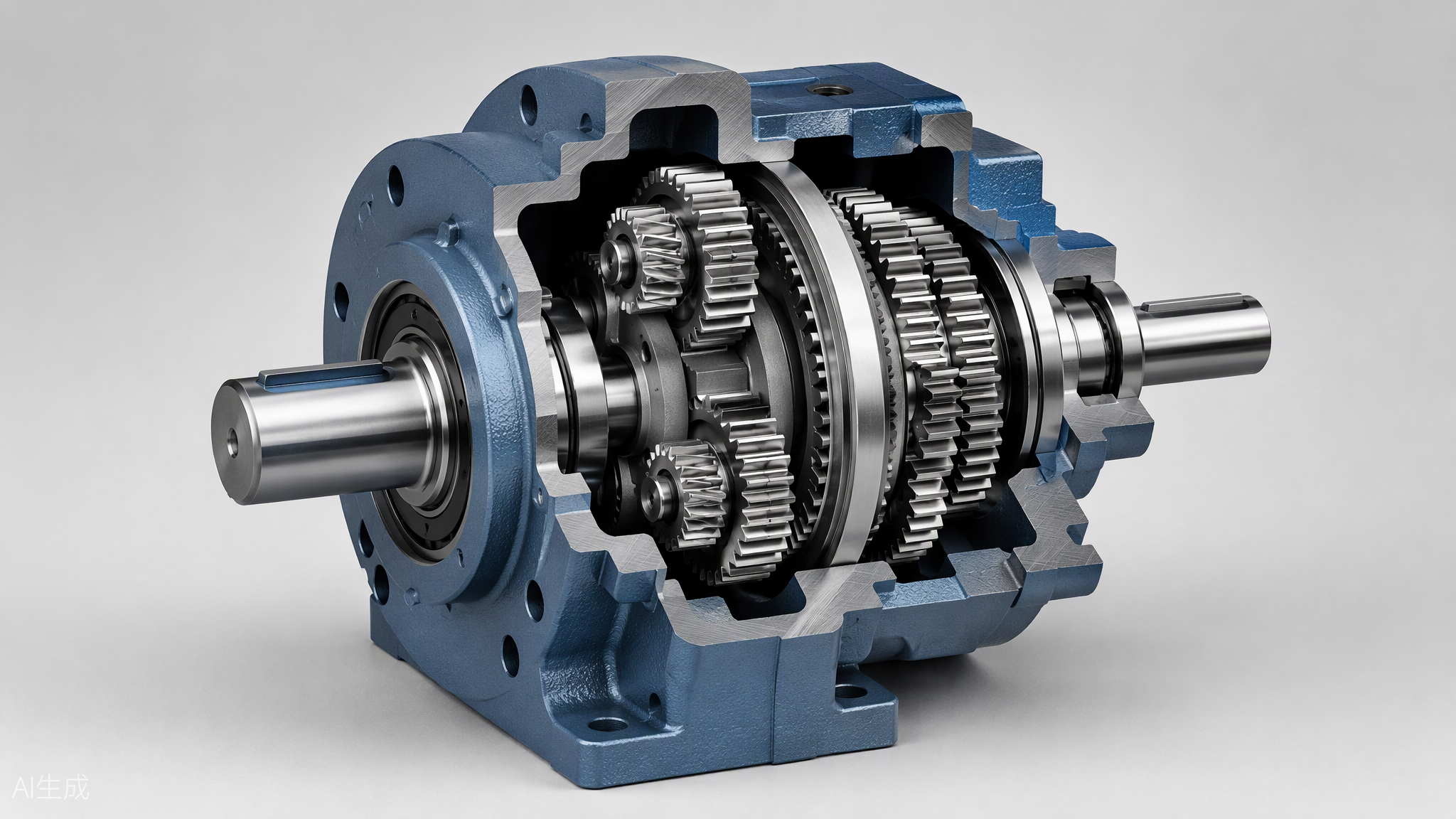
Gearbox Reducer vs. Slew Drive: Structural Principles, Parameters, and Application Scenarios Compared
Two speed-reduction mechanisms, two very different engineering worlds – a practical selection guide with real examples.
At first glance, a gearbox reducer and a slew drive seem to do the same job: both take the high-speed, low-torque output of a motor and convert it into low-speed, high-torque motion. Engineers sometimes even mix the names up in purchasing lists. Yet these two devices are built on different structural philosophies, deliver very different parameter profiles, and serve almost non-overlapping application scenarios. Choosing the wrong one can mean anything from poor efficiency and premature wear to a crane that cannot hold its boom. This article explains, in plain engineering language, how a gearbox reducer (also called a gear reducer or speed reducer gearbox) differs from a slew drive in structure, working principle, key parameters, and real-world use – with concrete examples for each.
1. What Is a Gearbox Reducer?
A gearbox reducer is a general-purpose speed reduction unit. Inside an enclosed cast-iron or aluminum housing, sets of gears – helical, bevel, planetary, or worm – mesh to reduce input speed and multiply output torque. The housing contains input and output shafts supported by ordinary rolling bearings, and the unit is bolted between a motor and the driven machine. The gear reducer itself only transmits torque along its shaft line; it is never expected to carry the weight of the machine or any overturning moment – external couplings, shafts, and bearings do that.
The working principle is straightforward: for a gear pair, the speed ratio equals the inverse of the teeth ratio, and output torque equals input torque multiplied by the ratio and the mesh efficiency. Different gear geometries create different families. A planetary gear reducer packs a sun gear, planet gears, and a ring gear into a coaxial layout, achieving 94-98% efficiency per stage, high torque density, and backlash as low as 1-3 arcmin – the favorite for servo and robotics work. A worm gear reducer uses a steel worm driving a bronze worm wheel at a right angle; a single stage can reach 60:1-100:1 and is often self-locking, at the cost of 50-90% efficiency. Interestingly, the same hardware family can run in reverse: the speed increaser gearbox in a wind turbine takes the 10-20 rpm of the rotor and raises it to the 1500 rpm a generator needs.
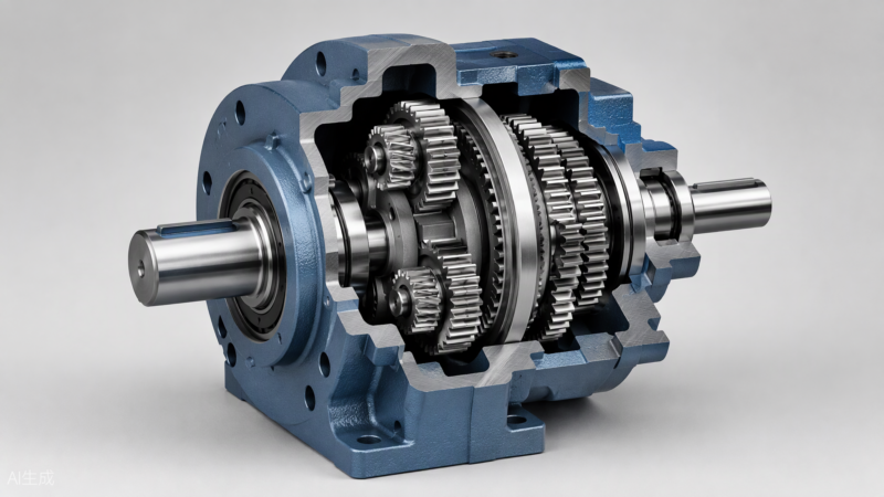
Fig. 1 – Cutaway of a planetary gear reducer: coaxial sun, planet, and ring gears deliver high torque density with 94-98% efficiency.
2. What Is a Slew Drive?
A slew drive (slewing drive) looks like a compact gearbox, but it is better understood as a complete rotary system. Its core is a slewing bearing – a large-diameter bearing whose inner or outer ring is machined with gear teeth – combined with a worm shaft, almost always of the hourglass (globoid) type for greater contact area. The worm, driven by an electric or hydraulic motor, slowly rotates the toothed bearing ring, and the whole structure bolted to that ring rotates with it.
The decisive structural difference: the slewing bearing is a structural bearing. It simultaneously carries axial load, radial load, and tilting moment – the overturning force that wind, gravity offset, or inertia applies to whatever sits on the ring. A standard speed reducer gearbox has no such capability at all. Everything sits inside a fully enclosed, grease-filled cast housing rated IP65 or IP66, so slew drives work outdoors for decades on solar farms, cranes, and antennas with almost zero maintenance. Output speed is extremely low – typically 0.01 to 1 rpm – and the hourglass worm mesh gives reliable self-locking, so the load stays exactly where it is even with the motor off.

Fig. 2 – A slew drive on a solar tracker: the hourglass worm drives the toothed slewing-bearing ring, which carries panels and wind moment loads directly.
3. Structural and Working-Principle Differences
Although both are speed-reduction mechanisms, five engineering differences separate them clearly:
- Bearing function. A gearbox reducer supports only its own shafts; the machine frame must carry all external loads. A slew drive is the bearing – the panel array, crane boom, or radar dish bolts straight onto the ring.
- Reduction ratio. A helical or planetary gear reducer works comfortably at 3:1-100:1 (multi-stage planetary units beyond 1000:1); a slew drive achieves 50:1-100:1 or more in a single worm stage because the ring gear has a very large pitch diameter.
- A planetary gear reducer wastes almost nothing (94-98% per stage). A slew drive’s worm mesh runs at roughly 30-40% – perfectly acceptable because a solar tracker or crane slews only minutes per day.
- Output motion. A gear reducer is designed for continuous rotation at tens to hundreds of rpm; a slew drive is designed for slow, intermittent, precisely held positioning.
- Self-locking and safety. Worm gear reducer units share the self-locking trick, but only the slew drive is specified and rated to hold static overturning moments as a primary safety function – a brake you never have to power.
4. Parameter Comparison at a Glance
| Parameter | Gearbox Reducer (Gear Reducer) | Slew Drive (Slewing Drive) |
| Reduction ratio | 3:1-100:1 per design; multi-stage planetary gear reducer can exceed 1000:1 | Typically 50:1-100:1 in a single worm stage |
| Transmission efficiency | Helical / planetary gear reducer: 94-98%; worm gear reducer: 50-90% | Worm mesh: roughly 30-40% (duty cycle is short, so this is acceptable) |
| Output speed | Continuous rotation, tens to hundreds of rpm | Very slow slewing, typically 0.01-1 rpm |
| Load capacity | Shaft torque rating; external bearings must carry radial / moment loads | Integrated slewing bearing carries axial load, radial load and tilting moment simultaneously |
| Self-locking | Only worm gear reducer designs (ratio dependent) | Yes – hourglass worm holds the load without a brake |
| Positioning precision | Planetary gear reducer: backlash down to 1-3 arcmin | 1-5 arcmin with preloaded worm; focus is holding accuracy, not dynamic precision |
| Typical input | Electric motor, servo motor, engine via coupling | Electric or hydraulic motor, 24 V DC common in tracking systems |
| Environment | Mostly indoor machinery, IP54 typical | Fully enclosed, grease-filled, IP65/IP66 for outdoor service |
5. Application Scenarios: Concrete Examples
5.1 Where the gearbox reducer wins
Conveyor systems. A packaging line needs its belt drum at 24 rpm from a 1450 rpm motor. A worm gear reducer with a 60:1 ratio delivers exactly that in a compact right-angle package, and its self-locking behavior keeps an inclined conveyor from rolling backward during a power cut. This is the classic speed reducer gearbox duty: continuous rotation, moderate ratio, indoor environment.
Robotics and servo axes. A six-axis robot joint demands a 100:1 ratio, 1-3 arcmin backlash, and high torque in minimal space. A two-stage planetary gear reducer paired with a servo motor is the standard answer – efficiency above 90% keeps heat down through thousands of duty cycles per hour.
Fig. 3 – Worm gear reducer cutaway: the steel worm and bronze wheel give right-angle output, high single-stage ratio, and self-locking.
Wind power. Inside a 2 MW wind turbine nacelle, a speed increaser gearbox proves the gear reducer family is bidirectional: the 15 rpm rotor enters the low-speed shaft, and three stages (one planetary, two helical) raise it to 1500 rpm for the generator – a 1:100 step-up that a slew drive could never provide efficiently.
5.2 Where the slew drive wins
Solar tracking systems. A single-axis tracker row may carry 30 tonnes of photovoltaic panels. A 9-inch class slew drive with a 24 V DC motor rotates the whole row at about 0.05 rpm to follow the sun, while its hourglass worm self-locks against storm gusts – the slewing bearing, not an external structure, absorbs the tilting moment. This is why nearly every modern tracking bracket uses slew drives instead of conventional gear reducers.
Truck cranes and aerial work platforms. Rotating a boom through 360 degrees with a load on the hook requires huge tilting-moment capacity and absolute holding safety. A hydraulic-motor slew drive gives both, replacing what would otherwise need a separate bearing, brake, and speed reducer gearbox.
Antennas and radar. A satellite ground-station dish must point to within arcminutes and hold that pose against wind. A precision slew drive with a preloaded worm provides smooth slow-motion tracking plus set-and-forget holding – a combination no off-the-shelf gear reducer can match.
6. How to Choose Between Them
The selection logic is simpler than the catalogs suggest. Ask three questions:
- Does the driven load need continuous rotation at working speed? If yes – choose a gearbox reducer (planetary gear reducer for precision and efficiency, worm gear reducer for high ratio and self-locking on a budget).
- Does the unit itself have to carry axial, radial, and overturning-moment loads, like a panel array, boom, or dish? If yes – only a slew drive will do; no speed reducer gearbox is designed for that.
- Is slow positioning with power-off holding the core requirement? If yes – the slew drive’s self-locking hourglass worm is the safest, simplest answer.
Modern designs increasingly combine the two: a small planetary input stage ahead of the worm raises total ratio and improves efficiency, showing that the two families complement rather than replace each other.
Conclusion
A gearbox reducer and a slew drive share the same DNA – reduce speed, multiply torque – but they are different organisms. The gear reducer is a high-efficiency torque transmission for continuously rotating machinery; the slew drive is a structural rotary joint that carries, positions, and locks entire assemblies. Match the device to the load and the duty cycle, and each will deliver decades of reliable service in the role it was built for.
Leave A Comment